
Blog
What Is a Cleanroom Chiller System?
A Cleanroom Chiller System supports the temperature and humidity conditions required by controlled production spaces. It cools chilled water for air-handling units, which then condition air moving through filters and cleanroom zones. The chiller does not remove particles itself. That distinction matters: filtration, airflow, pressure control, and cooling must work together.
The requirements can be precise. ISO 14644-1:2015 sets airborne particle concentration limits by cleanroom classification; for ISO Class 5, the limit is 3,520 particles of 0.5 micrometers or larger per cubic meter. This is a useful design reference, not a guarantee of performance. ASHRAE’s Handbook—HVAC Applications also addresses clean spaces and their environmental-control needs. These sources show why equipment selection should follow the room’s classification, process heat load, and operating schedule—not just its floor area.
In practice, engineers assess peak cooling demand, redundancy, water temperatures, and humidity-control strategy. A semiconductor tool may release heat steadily, while a pharmaceutical room can see changing occupancy and process loads. A chiller that is oversized may cycle inefficiently; one that is undersized can struggle during peak operation. There is no universal recipe. Even a well-designed system needs commissioning and ongoing checks, because filters, valves, and operating conditions change. That is the less tidy part. The sections ahead explain how the system works, which components matter, and what to consider when specifying one.
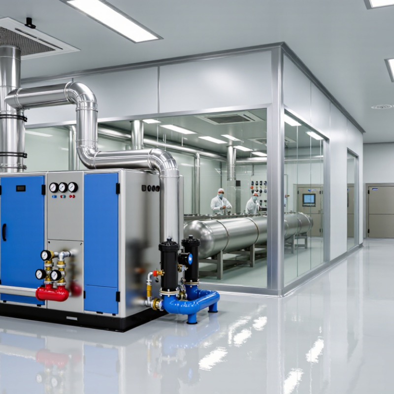
Cleanroom Chiller Systems: Definition and Purpose
A cleanroom chiller system is a cooling arrangement that removes heat from cleanroom spaces and process equipment. It typically includes a chiller, pumps, piping, and cooling coils in air-handling units. The chiller cools water, which flows through the coils and helps control room temperature. Some systems also support equipment that produces steady heat, such as laboratory instruments or manufacturing machinery. The chiller itself does not remove airborne particles. Not the whole solution.
Its purpose is to keep environmental conditions within the limits required by the room’s work. Stable cooling can help reduce temperature swings that affect sensitive processes, materials, or instruments. In many facilities, the system operates alongside filtration, humidity control, and room-pressure management. Those functions need to be coordinated, not treated as separate afterthoughts. For example, a loaded air filter or a change in equipment use can alter airflow and heat levels. Small changes matter. System capacity should be based on actual heat loads and operating schedules, then checked through routine monitoring. A cooling design can look adequate on paper and still perform unevenly across rooms. That gap deserves attention. Temperature readings, water-flow checks, and maintenance records help teams spot problems before conditions drift too far.
What Is a Cleanroom Chiller System? - Cleanroom Chiller Systems: Definition and Purpose
A cleanroom chiller system removes heat from chilled water or another cooling fluid and supplies it to air-handling equipment or process loads. The values below are general examples; actual specifications depend on the facility, process, climate, and applicable standards.
| Data Dimension | Description or Typical Data | Purpose in a Cleanroom |
|---|---|---|
| System definition | A refrigeration system that cools circulating water or another heat-transfer fluid for use by HVAC coils or equipment. | Provides a controlled source of cooling for cleanroom environmental conditioning and, where required, process equipment. |
| Primary heat-transfer path | Chiller evaporator → chilled-water piping → cooling coil or process load → return piping → chiller. | Moves heat from the cleanroom or process to the chiller, where it is rejected outdoors or to a heat-recovery system. |
| Typical chilled-water temperatures | Approximately 6–7°C supply and 11–13°C return are common design examples. Some systems use different temperatures to suit their loads. | Supplies cooling to air-handling-unit coils; the final design temperature is determined by load, coil selection, and humidity-control requirements. |
| Cooling capacity | Project-specific, ranging from small capacities for localized loads to large capacities for multi-zone facilities. Capacity is selected through a cooling-load calculation. | Matches the combined cooling demand, including people, lighting, equipment, outdoor air, and process heat. |
| Typical system components | Chiller, pumps, piping, valves, strainers, expansion vessel, controls, and—depending on the design—a cooling tower or air-cooled heat-rejection section. | Circulates the cooling fluid, manages pressure and flow, removes heat, and supports safe, stable operation. |
| Cleanroom air-handling connection | Chilled water commonly serves cooling coils in air-handling units (AHUs). The AHU may also include fans, filters, and other air-treatment equipment. | Allows the HVAC system to cool and condition supply air before it enters the cleanroom. |
| Temperature control | Room and supply-air targets are set by the facility design and process needs; there is no single temperature suitable for every cleanroom. | Helps maintain conditions required for personnel comfort, product quality, equipment operation, and process stability. |
| Humidity control | Chilled-water cooling can support dehumidification when air is cooled below its dew point. Reheat or other controls may be needed to achieve the required supply conditions. | Supports humidity management, but humidity control is a function of the complete HVAC system—not the chiller alone. |
| Particle cleanliness | A chiller does not filter or sterilize cleanroom air. Particle control is provided by the cleanroom air-distribution design and filtration system. | Keeps the roles of cooling equipment and cleanroom filtration distinct while allowing both systems to work together. |
| Water-side design considerations | Designers account for required flow, pressure drop, water quality, corrosion protection, insulation, condensate management, and leak detection where appropriate. | Helps maintain reliable heat transfer and reduces risks such as leaks, corrosion, and unwanted condensation. |
| Reliability and redundancy | Critical facilities may use standby capacity, multiple pumps or chillers, backup power, alarms, and planned maintenance provisions. | Reduces the impact of equipment failure or maintenance on temperature-sensitive operations. |
| Monitoring and controls | Common monitored points include supply and return water temperatures, flow, pressure, operating status, alarms, and energy use. | Enables operators to verify performance, identify faults, and coordinate chiller operation with the building management system. |
| Energy efficiency | Efficiency depends on load, outdoor conditions, equipment selection, part-load performance, pumping, and heat-rejection design. | Appropriate sizing, sequencing, variable-speed control, and regular maintenance can help reduce energy consumption. |
| Design basis | Final requirements should be established through project-specific load calculations, cleanroom classification needs, process requirements, and applicable codes and standards. | Ensures the chiller system supports the facility’s actual environmental and operational requirements. |