How to Choose 480V to 13.8kV Step Up Transformer Specs?
Selecting a 480V to 13.8kV transformer is not a ratio-only exercise. The 480v To 13.8kv Step-Up Power Transformer Specs must match the site’s load profile, protection system, and operating environment. The voltage ratio is approximately 28.75:1, but kVA capacity determines the actual current and thermal burden. A 1,000 kVA unit delivers about 41.7 A at 13.8 kV, excluding losses. That figure changes protection settings significantly.
Industry demand is becoming less predictable. The U.S. Energy Information Administration’s Short-Term Energy Outlook reports continued electricity-demand growth, influenced by data centers, manufacturing, and electrification. The U.S. Department of Energy’s Electric Grid Supply Chain Review also identifies large transformers as critical, long-lead grid components. These findings support conservative specification, spare-parts planning, and early factory coordination. Waiting for a nameplate after procurement is risky.
This guide examines kVA selection, impedance, primary and secondary taps, BIL, insulation class, cooling, grounding, and harmonic performance. IEEE C57.12.00 and IEC 60076 provide important design and testing references. Site experience still matters. Dust, salt air, altitude, ambient temperature, and frequent motor starting can invalidate a laboratory-perfect selection. A transformer may meet its voltage rating yet fail the project’s short-circuit or voltage-drop expectations. That uncomfortable gap deserves attention. We also consider mineral-oil and dry-type designs, enclosure requirements, maintenance access, and utility interconnection criteria. Final approval should come from a qualified engineer after reviewing measured loads, fault studies, and local electrical requirements.
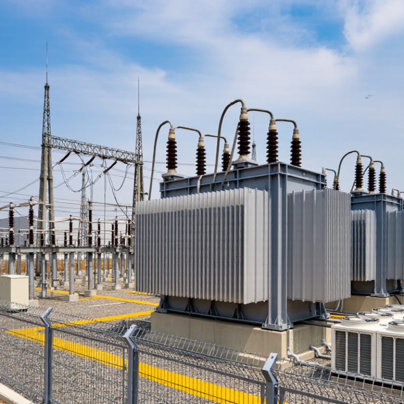
Define the 480V and 13.8kV Transformer Application Requirements
A 480V-to-13.8kV step-up transformer must match the complete application, not only the voltage labels. Confirm the source voltage, frequency, available fault current, and load type at 480V. Motors, rectifiers, and variable-frequency drives can create high starting currents and harmonic heating. Record normal, peak, and future loads in kVA. A brief motor-starting event may require more capacity than the average load suggests.
At 13.8kV, define the utility connection, grounding method, insulation level, and required Basic Insulation Level. Outdoor installations need weather protection, suitable cooling, and corrosion resistance. Indoor units require ventilation and fire-safety coordination. The U.S. Department of Energy’s Distribution Transformer Technical Support Document estimates annual U.S. distribution-transformer losses near 61 billion kWh. That figure supports careful evaluation of no-load losses, load losses, and expected operating hours. Efficiency matters, but oversizing also increases idle losses. This is often overlooked.
Tips: Build a 24-hour load profile before selecting the rating. Ask for impedance tolerance, short-circuit withstand data, temperature-rise limits, and factory test records. Check harmonics with measured data, not assumptions. IEEE guidance and applicable IEC or national standards should shape the specification. A practical review should include future expansion, but forecasts can be wrong. Leave enough margin without paying for unused steel and copper.
Calculate Capacity, Load Demand, and Voltage Regulation
Choosing a 480V to 13.8kV step-up transformer starts with actual load demand, not the largest motor on the drawing. List each load, its rated kW, power factor, duty cycle, and starting method. Calculate running demand using kVA = kW ÷ power factor. For three-phase systems, verify current with kVA = √3 × voltage × amps ÷ 1,000. Add continuous loads carefully. Do not simply total every nameplate value.
Motor starting can change the specification. A large motor may draw five to seven times its running current, causing temporary voltage sag. Include starting kVA, sequential starting, and the weakest operating condition. A practical design may include 10–20% spare capacity for expansion, but excessive margin can increase cost and reduce efficiency. A neat calculation can still be wrong.
Voltage regulation deserves equal attention. It describes the secondary voltage change between no-load and full-load conditions. A transformer with 5% impedance may limit fault current, yet produce noticeable voltage drop during heavy demand. Check the 480V source, cable length, conductor size, transformer impedance, and 13.8kV utility requirements together. Tap settings must match the measured supply voltage, not an assumed value. Confirm insulation levels, frequency, cooling class, temperature rise, and short-circuit withstand ratings from certified test documents. Have a qualified engineer review the final load study. Field measurements often reveal unbalanced phases or higher starting demand than the original design.
480V to 13.8kV Step-Up Transformer Sizing
Example calculation for a 1,250 kVA transformer. Connected load is 1,150 kVA, diversified peak demand is 915 kVA, and a 10% future-growth case reaches 1,007 kVA. Estimated voltage regulation is calculated with VR ≈ R% × cosφ + X% × sinφ, using 1.0% resistance and 5.66% reactance.
The selected 1,250 kVA rating provides approximately 73.2% utilization at diversified peak demand and 80.6% utilization with 10% growth. At a 0.90 lagging power factor, estimated voltage regulation is about 3.4%, which supports stable secondary voltage when conductor impedance and starting transients are properly evaluated.
Select Phase, Frequency, Impedance, and Connection Specifications
Selecting a 480V to 13.8kV step-up transformer starts with the actual system phase. Most industrial installations use three-phase power because motors and distribution equipment require balanced loading. Confirm the source phase count, load capacity, and available fault current before requesting a quotation. A mismatch here can make an otherwise correct transformer unusable.
Frequency must match the incoming supply. A 60 Hz transformer should not be casually applied to a 50 Hz system. Lower frequency can increase core flux, heating, and no-load current.
Impedance also deserves careful attention. A common range may be suitable, but the correct value depends on motor starting, voltage regulation, and short-circuit limits. Higher impedance reduces fault current but may cause greater voltage drop during a large motor start. Measure the real load profile.
Connection specifications affect protection and grounding. A delta primary and grounded-wye secondary are often considered for medium-voltage distribution, but the best arrangement depends on utility rules, harmonics, and grounding practice.
Specify the required vector group, neutral access, and phase displacement. Field engineers should verify relay settings against the transformer impedance and connection.
Small details matter. A neat spreadsheet can still miss future expansion, and I have seen projects overlook standby loads. Recheck every assumption.
Evaluate Insulation, Cooling, Enclosure, and Safety Requirements
A 480V-to-13.8kV transformer needs more than a matching voltage ratio. Insulation selection should begin with system voltage, impulse exposure, altitude, humidity, and contamination. For medium-voltage windings, request a documented basic insulation level and verified clearances. A dry indoor room may allow different materials than a dusty outdoor substation. Inspect creepage paths, surge protection, and test records before accepting the specification. Small gaps matter. I would not rely on a catalog rating alone. Request routine and type test reports against applicable IEC or IEEE requirements.
Load profile drives cooling. A transformer feeding motors may face repeated starting currents, while a steady industrial load behaves differently. Compare temperature-rise limits, ambient design temperature, and expected overload duration. Natural-air cooling can reduce maintenance, but fans may be necessary in compact enclosures. Keep radiators and ventilation openings clear; blocked airflow can quietly shorten insulation life. Ask how alarms, fan failure, and winding-temperature sensors will be tested. This detail is often missed during procurement.
The enclosure should match its location, not merely its appearance. Specify indoor or outdoor service, ingress protection, corrosion resistance, cable entry, and grounding points. A lockable high-voltage compartment, visible warning labels, and interlocked access reduce human error. Confirm the grounding design with a qualified engineer and local electrical requirements. Include pressure relief and fire considerations where applicable. One practical check remains: can technicians isolate, test, and inspect the transformer without entering an unsafe zone? The answer may expose weaknesses in an otherwise impressive specification.
Verify Standards, Installation Conditions, and Protection Coordination
Choosing a 480V to 13.8kV step-up transformer starts with verified standards, not only the voltage ratio. Confirm applicable electrical codes, transformer standards, insulation levels, grounding rules, and utility requirements. The nameplate should state rated power, frequency, impedance, tap range, temperature rise, and basic impulse insulation level. Ask for routine and design test records from a qualified manufacturer.
Installation conditions can change the specification. Record the site altitude, ambient temperature, humidity, dust, salt exposure, and available ventilation. A transformer beside a hot process line may need derating. Check clearance around bushings, cable bending space, fire separation, oil containment, and lifting access. Small details matter. I have seen layouts pass electrical review but fail during cable pulling. That mistake is expensive.
Protection coordination must consider both sides of the transformer. Set medium-voltage relays, fuses, and breakers to protect against faults without unnecessary trips. Review inrush current, transformer damage curves, through-fault withstand, ground-fault current, and downstream motor starting. Coordinate the 480V main breaker with the 13.8kV protective device using actual time-current curves. Do not rely on default relay settings. A study should include arc-flash calculations and grounding design, completed by a licensed engineer where required. Recheck assumptions when the utility fault level changes. That happens more often than expected.